P4-based User Plane Function (P4-UPF)
Overview
SD-Fabric supports running a 4G/5G mobile core User Plane Function (UPF) as part of the switches packet processing pipeline. Like the rest of the pipeline, this is realized using P4 and for this reason we call this P4-UPF.
P4-UPF is integrated with the ONF’s SD-Core project. By default, SD-Core ships with BESS-UPF, a containerized UPF implementation, based on the Berkeley Software Switch (BESS).
SD-Fabric can be used with BESS-UPF or any other UPF implementation that runs on servers. In this case, the fabric switches can provide routing of GTP-U packets to and from radio base station and servers. When P4-UPF is enabled, the same fabric switches perform GTP-U tunnel termination.

Supported Features
SD-Fabric’s P4-UPF implements a core set of features capable of supporting requirements for a broad range of enterprise use cases:
GTP-U tunnel encap/decap: including support for 5G extensions such as PDU Session Container carrying QoS Flow Information.
Accounting: we use switch counters to collect per-flow stats and support usage reporting and volume-based triggers.
Downlink buffering: when a user device radio goes idle (power-save mode) or during a handover, switches are updated to forward all downlink traffic for the specific device (UE) to DBUF, a K8s-managed buffering service running on servers. Then, when the device radio becomes ready to receive traffic, packets are drained from the software buffers back to the switch to be delivered to base stations.
QoS: support for enforcement of maximum bitrate (MBR) at the application, session, and slice level; and prioritization using switch queues and scheduling policy.
Slicing: multiple logical UPFs can be instantiated on the same switch, each one with its own QoS model and isolation guarantees enforced at the hardware level using separate queues.
Distributed UPF
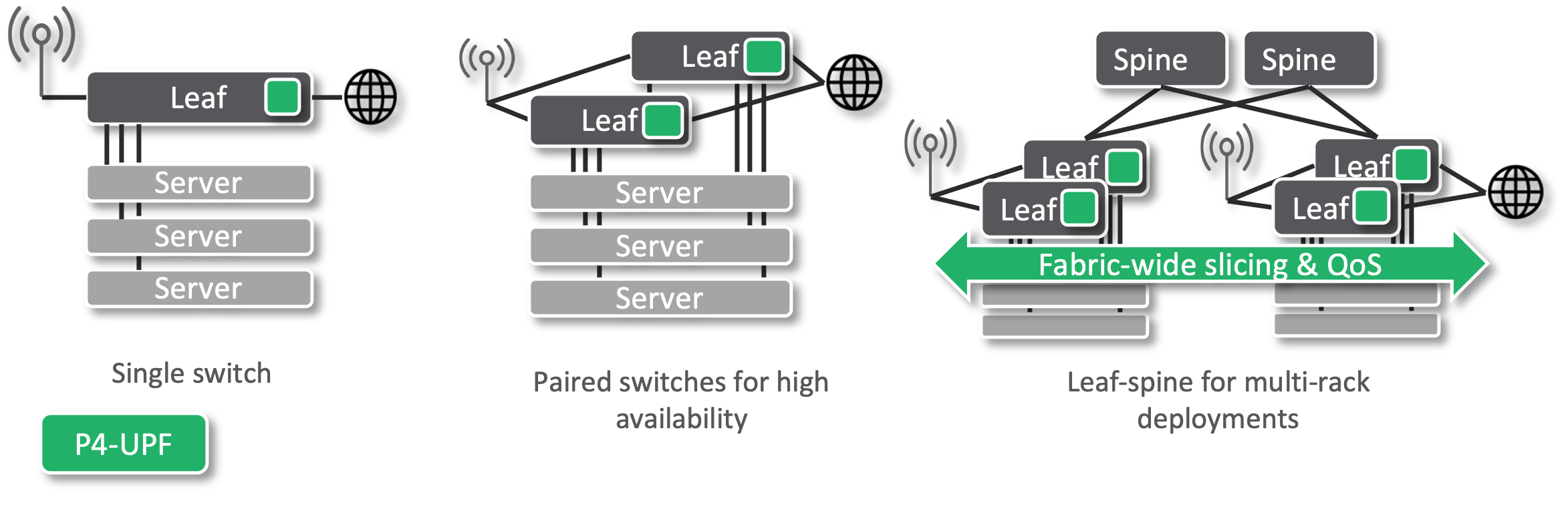
In SD-Fabric we support different topologies to meet the requirements of different deployment sizes: from a single rack with just one leaf switch, or a paired-leaves for redundancy, to N x M leaf-spine fabric for multi-rack deployments. For this reason, P4-UPF is realized with a “distributed” data plane implementation where all leaf switches are programmed with the same UPF rules, such that any leaf can terminate any GTP-U tunnel. This provides several benefits:
Simplified deployment: base stations can be connected via any leaf switch.
Minimum latency: the UPF function is applied as soon as packets enter the fabric, without going through additional devices before reaching their final destination.
Fast failover: when using paired-leaves, if one switch fails, the other can immediately take over as it is already programmed with the same UPF state.
Fabric-wide slicing & QoS guarantees: packets are classified as soon as they hit the first leaf. We then use a custom DSCP-based marking to enforce the same QoS rules on all hops. In case of congestion, flows deemed high priority are treated as such by all switches.
Control Architecture and Integration with SD-Core
SD-Fabric’s P4-UPF is integrated with the ONF SD-Core project to provide a high-performance 3GPP-compliant mobile core solution.
The integration with SD-Core is achieved via an ONOS application called UP4, which is in charge of populating the UPF tables of the switch pipeline.
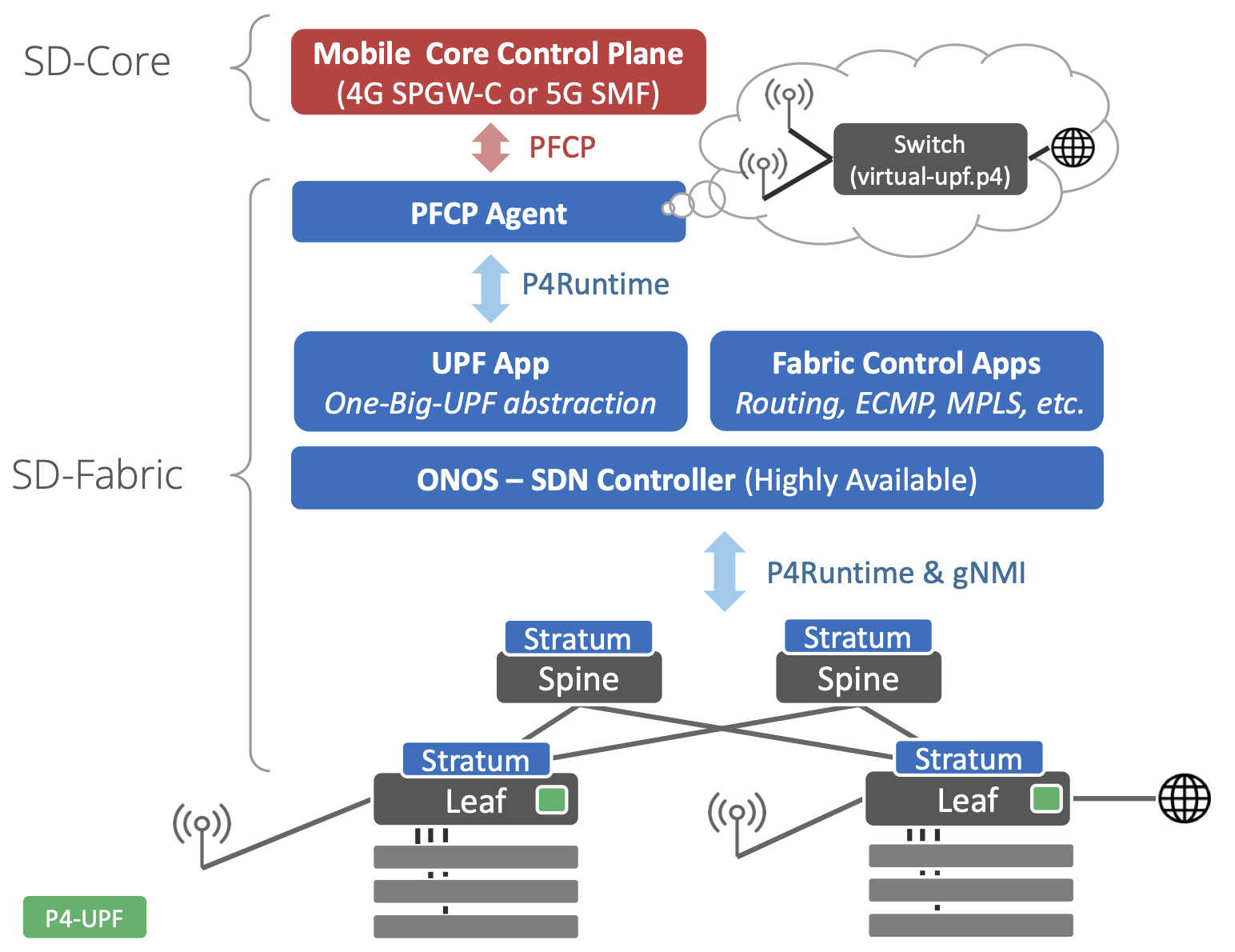
The interface between the mobile core control plane and the UPF is defined by the 3GPP standard Packet Forwarding Control Protocol (PFCP). This is a complex protocol that can be difficult to understand, even though at its essence the rules that it installs are simple match-action rules. The implementation of such protocol, such as message parsing, state machines, and other bookkeeping can be common to many different UPF realizations. For this reason, SD-Fabric relies on an implementation of the PFCP protocol realized as an external microservice named “PFCP Agent”, which is provided by the SD-Core project.
The UP4 App abstracts the whole fabric as one virtual big switch with UPF capabilities, we call this the One-Big-UPF abstraction. Such abstraction allows the upper layers to be independent of the underlying physical topology. Communication between the PFCP Agent and the UP4 App is done via P4Runtime. This is the same API that ONOS uses to communicate with the actual switches. However, in the former case, it is used between two control planes, the mobile core, and the SDN controller. By doing this, the deployment can be scaled up and down, adding or removing racks and switches, without changing the mobile core control plane, which instead is provided with the illusion of controlling just one switch.
The One-Big-UPF abstraction abstraction is realized with a virtual-upf.p4
program that formalizes the forwarding model described by PFCP as a series of
match-action tables. This program doesn’t run on switches, but it’s used as the
schema to define the content of the P4Runtime messages between PFCP Agent and
the UP4 App. On switches, we use a different program, fabric.p4, which
implements tables similar to the virtual UPF but optimized to satisfy the
resource constraints of Tofino, as well as tables for basic bridging, IP
routing, ECMP, and more. The UP4 App implements a P4Runtime server, like if it
were a switch, but instead it internally takes care of translating P4Runtime
rules from virtual-upf.p4 to rules for the multiple physical switches running
fabric.p4, based on an up-to-date global view of the topology.
Downlink Buffering (DBUF)
A UPF is required to buffer packets when UEs are in idle-mode or during handovers, this is usually called downlink buffering, as it applies only to the downlink direction of traffic. Most switches provide buffering capabilities to handle congestion, they cannot hold packets indefinitely. For this reason, we provide DBUF, a microservice responsible for providing the downlink buffering capabilities to P4-UPF.
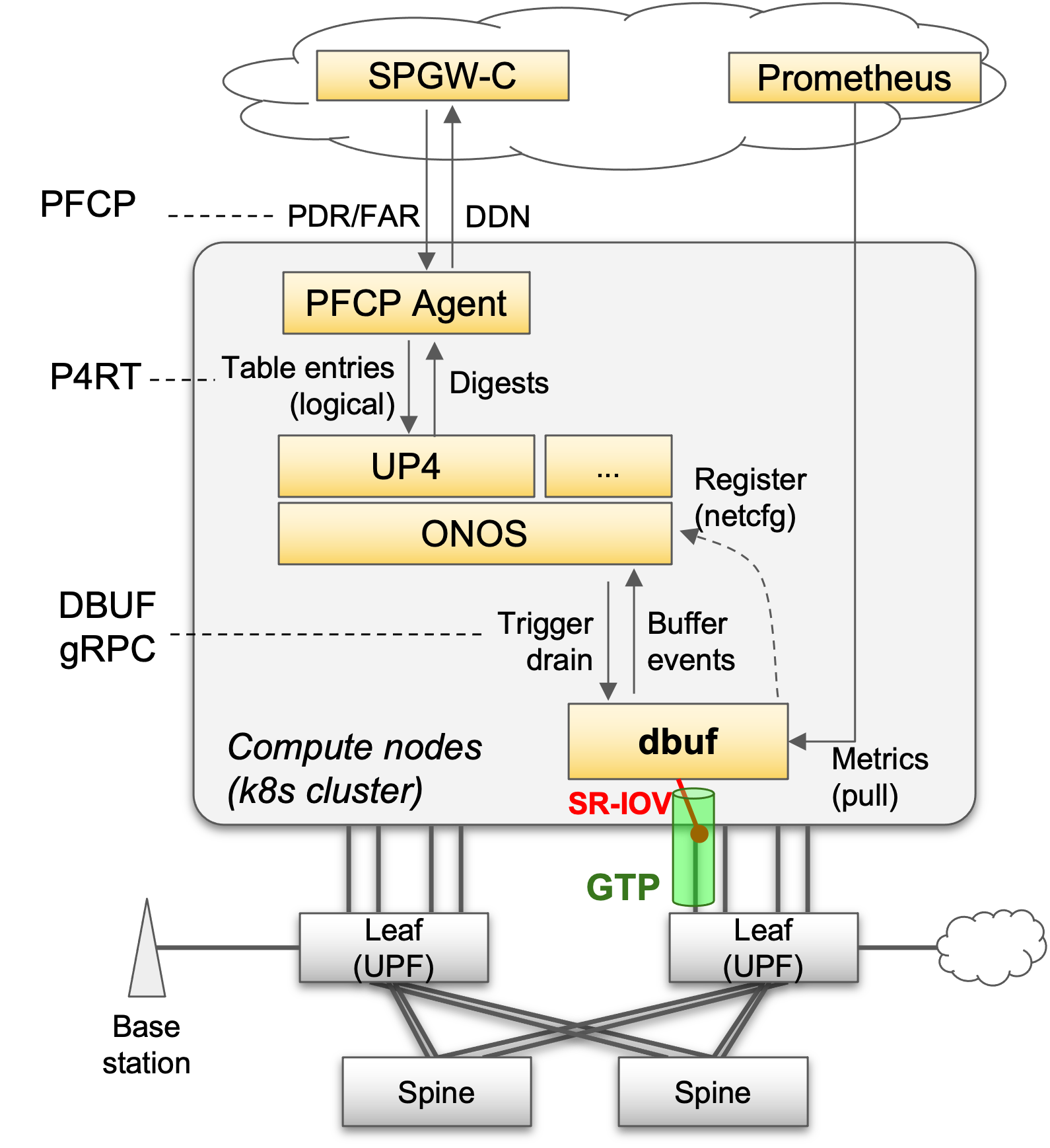
When a UE goes idle and turns off its radio, or during handovers, the mobile core control plane uses PFCP to update the Forwarding Action Rules (FARs) for that UE to enter buffering* mode. When this happens, UP4 updates the switch rules to steer packets to DBUF using GTP-U tunnels.
UP4 uses gRPC to communicate with DBUF. DBUF notifies UP4 about buffering events, which are relayed to the mobile core control plane as Downlink Data Notifications (DDN). When a UE becomes available again, UP4 triggers a buffer drain on DBUF and updates the switch rules to start sending traffic to the UE again.
Deploying DBUF is optional (can be enabled in the SD-Fabric Helm Chart). DBUF feature requires SR-IOV and DHCP support on NICs and Kubernetes CNIs.
ONOS Configuration
The UPF configuration is split in two configurations, that can be provided independently to ONOS. Th first is used to configure the UP4 ONOS application and defines UPF-related information such as S1U Address, network devices implementing UPF etc. The second one, instead, is used to configure parameters related to the DBUF functionality.
Here’s a list of fields that you can configure via the UPF Network Configuration for UP4:
devices: A list of devices IDs that implements the UPF data plane. This list must include all the leaf switches in the topology. The UPF state is replicated on all devices specified in this configuration field. The devices specified in this list must use a P4 pipeline implementing the UPF functionality. Requireds1uAddr: Deprecated. Usen3Addrinstead.n3Addr: The IP address of the N3 interface (equivalent to S1-U for 4G). It can be an arbitrary IP address. Optional (PFCP agent can insert interface table entry if not supplied)uePools: A list of subnets that are in use by the UEs. Optional (PFCP agent can insert interface table entry if not supplied)sliceId: Network slice ID used by mobile traffic. Optional Required only when eithern3AddroruePoolsis specified.dbufDrainAddr: The IP address of the UPF data plane interface that the DBUF service will drain packets towards. OptionalpscEncapEnabled: Set whether the UPF should use GTP-U extension PDU Session Container when doing encapsulation of downlink packets. Optional (Should set to true for 5G)defaultQfi: The default QoS Flow Identifier to use when the PDU Session Container encapsulation is enabled. Optional
Here is an example of netcfg JSON for UP4:
{
    "apps": {
        "org.omecproject.up4": {
            "up4": {
              "devices": [
                "device:leaf1",
                "device:leaf2"
              ],
              "n3Addr": "10.32.11.126",
              "uePools": [
                "10.240.0.0/16"
              ],
              "sliceId": 0
              "dbufDrainAddr": "10.32.11.126",
              "pscEncapEnabled": false,
              "defaultQfi": 0
            }
        }
    }
}
The DBUF configuration block is all Optional, we can use UP4 without the downlink buffering functionality. Here’s a list of fields that you can configure:
serviceAddr: The address of the DBUF service management interface in the form IP:port. This address is used to communicate with the DBUF service via gRPC (for example, to trigger the drain operation, or receive notification for buffered packets).dataplaneAddr: The address of the DBUF service data plane interface in the form IP:port. Packets sent to this address by the UPF switches will be buffered by DBUF. The IP address must be a routable fabric address.
Here is an example of netcfg for DBUF:
{
    "apps": {
        "org.omecproject.up4": {
            "dbuf": {
                "serviceAddr": "10.76.28.72:10000",
                "dataplaneAddr": "10.32.11.3:2152"
            }
      }
    }
}
Note
When deploying DBUF using the SD-Fabric Helm Chart you do NOT need to
provide the "dbuf" part of the UP4 config. That will be pushed
automatically by the DBUF Kubernetes pod.
PFCP Agent Configuration
PFCP Agent can be deployed as part of the SD-Fabric Helm Chart.
See the SD-Fabric Helm Chart README for more information on the configuration
parameters used in SD-Fabric.
See the PFCP agent configuration guide <https://github.com/omec-project/upf/blob/master/docs/configuration_guide.md> for other parameters provided by PFCP agent.
Once deployed, use kubectl get services -n sdfabric to find out
the exact UDP endpoint used to listen for PFCP connection requests.