Dual Homing
Overview
The dual-homing feature includes several sub components
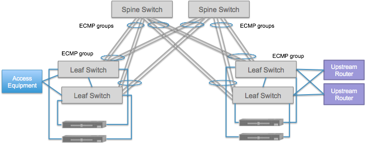
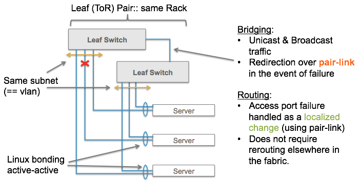
Use of “paired” ToRs: Each rack of compute nodes have exactly two Top-of-Rack switches (ToRs), that are linked to each other via a single link - such a link is referred to as a pair link. This pairing should NOT be omitted.
Currently there is support for only a single link between paired ToRs. In future releases, we may include dual pair links. Note that the pair link is only used in failure scenarios, and not in normal operation.
Dual-homed servers (compute-nodes): Each server is connected to both ToRs. The links to the paired ToRs are (Linux) bonded
Dual-homed upstream routers: The upstream routers MUST be connected to the two ToRs that are part of a leaf-pair. You cannot connect them to leafs that are not paired. This feature also requires two Quagga instances.
Dual-homed access devices. This component will be added in the future.
Paired ToRs
The reasoning behind two ToR (leaf) switches is simple. If you only have a single ToR switch, and you lose it, the entire rack goes down. Using two ToR switches increases your odds for continued connectivity for dual homed servers. The reasoning behind pairing the two ToR switches is more involved, as is explained in the Usage section below.
Configure pair ToRs
Configuring paired-ToRs involves device configuration. Assume switches of:205 and of:206 are paired ToRs.
{
  "devices" : {
    "of:0000000000000205" : {
      "segmentrouting" : {
        "name" : "Leaf1-R2",
        "ipv4NodeSid" : 205,
        "ipv4Loopback" : "192.168.0.205",
        "ipv6NodeSid" : 205,
        "ipv6Loopback" : "2000::c0a8:0205",
        "routerMac" : "00:00:02:05:00:01",
        "pairDeviceId" : "of:0000000000000206",
        "pairLocalPort" : 20,
        "isEdgeRouter" : true,
        "adjacencySids" : []
      }
    },
    "of:0000000000000206" : {
      "segmentrouting" : {
        "name" : "Leaf2-R2",
        "ipv4NodeSid" : 206,
        "ipv4Loopback" : "192.168.0.206",
        "ipv6NodeSid" : 206,
        "ipv6Loopback" : "2000::c0a8:0206",
        "routerMac" : "00:00:02:05:00:01",
        "pairDeviceId" : "of:0000000000000205",
        "pairLocalPort" : 30,
        "isEdgeRouter" : true,
        "adjacencySids" : []
      }
    }
  }
}
There are two new pieces of device configuration.
Each device in the ToR pair needs to specify the deviceId of the leaf it is
paired to, in the pairDeviceId field. For example, in of:205
configuration the pairDeviceId is specified as of:206, and similarly in of:206
configuration the pairDeviceId is of:205. Each device in the ToR pair needs to
specify the port on the device used for the pair link in the
pairLocalPort field. For example, the pair link in the config above show
that port 20 on of:205 is connected to port 30 on of:206.
In addition, there is one crucial piece of config that needs to match for
both ToRs – the routerMac address. The paired-ToRs MUST have the same
routerMac - in the example above, they both have identical 00:00:02:05:00:01
routerMac.
All other fields are the same as before, as explained in Device Configuration section.
Usage of pair link
Dual-Homed Servers
There are a number of things to note when connecting dual-homed servers to paired-ToRs.
The switch ports on the two ToRs have to be configured the same way, when connecting a dual-homed server to the two ToRs.
The server ports have to be Linux-bonded in a particular mode.
Configure Switch Ports
The way to configure ports are similar as described in Bridging and Unicast. However, there are a couple of things to note.
First, dual-homed servers should have the identical configuration on each
switch port they connect to on the ToR pairs. The example below shows that
the vlans and ips configured are the same on both switch ports
of:205/12 and of:206/29. They are both configured to be access ports
in VLAN 20, the subnet 10.0.2.0/24 is assigned to these ports, and the
gateway-IP is 10.0.2.254/32.
{
  "ports" : {
    "of:0000000000000205/12" : {
      "interfaces" : [{
        "name" : "h3-intf-1",
        "ips" : [ "10.0.2.254/24"],
        "vlan-untagged": 20
      }]
    },
    "of:0000000000000206/29" : {
      "interfaces" : [{
        "name" : "h3-intf-2",
        "ips" : [ "10.0.2.254/24"],
        "vlan-untagged": 20
      }]
    }
  }
}
It is worth noting the meaning behind the configuration above from a routing
perspective. Simply put, by configuring the same subnets on these switch
ports, the fabric now believes that the entire subnet 10.0.2.0/24 is
reachable by BOTH ToR switches of:205 and of:206.
Caution
Configuring different VLANs, or different subnets, or mismatches like
vlan-untagged in one switch port and vlan-tagged in the corresponding
switch port facing the dual-homed server, will result in incorrect
behavior.
Second, we need to configure the pair link ports on both ToR switches to be trunk (``vlan-tagged``) ports that contains all dual-homed VLANs and subnets. This is an extra piece of configuration, the need for which will be removed in future releases. In the example above, a dual-homed server connects to the ToR pair on port 12 on of:205 and port 29 on of:206. Assume that the pair link between the two ToRs is connected to port 5 of both of:205 and of:206. The config for these switch ports is shown below:
{
  "ports": {
    "of:0000000000000205/5" : {
      "interfaces" : [{
          "name" : "205-pair-port",
          "ips" : [ "10.0.2.254/24"],
          "vlan-tagged": [20]
      }]
    },
    "of:0000000000000206/5" : {
      "interfaces" : [{
        "name" : "206-pair-port",
        "ips" : [ "10.0.2.254/24"],
        "vlan-tagged": [20]
      }]
    }
  }
}
Note
Even though the ports of:205/12 and of:206/29 facing the dual-homed
server are configured as vlan-untagged, the same VLAN MUST be
configured as vlan-tagged on the pair-ports.
If additional subnets and VLANs are configured facing other dual-homed
servers, they need to be similarly added to the ips and vlan-tagged
arrays in the pair port config.
Configure Servers
Assuming the interfaces we are going to use for bonding are eth1 and eth2.
Bring down interfaces
$ sudo ifdown eth1
$ sudo ifdown eth2
Modify
/etc/network/interfacesauto bond0 iface bond0 inet dhcp bond-mode balance-xor bond-xmit_hash_policy layer2+3 bond-slaves none auto eth1 iface eth1 inet manual bond-master bond0 auto eth2 iface eth2 inet manual bond-master bond0
Start interfaces
$ sudo ifup bond0
$ sudo ifup eth1
$ sudo ifup eth2
Useful command to check bonding status
# cat /proc/net/bonding/bond0
Ethernet Channel Bonding Driver: v3.7.1 (April 27, 2011)

Bonding Mode: load balancing (xor)
Transmit Hash Policy: layer2+3 (2)
MII Status: up
MII Polling Interval (ms): 0
Up Delay (ms): 0
Down Delay (ms): 0

Slave Interface: eth1
MII Status: up
Speed: 1000 Mbps
Duplex: full
Link Failure Count: 0
Permanent HW addr: 00:1c:42:5b:07:6a
Slave queue ID: 0

Slave Interface: eth2
MII Status: up
Speed: Unknown
Duplex: Unknown
Link Failure Count: 0
Permanent HW addr: 00:1c:42:1c:a1:7c
Slave queue ID: 0
Caution
Dual-homed host should not be statically configured.
Currently in ONOS, configured hosts are not updated when the connectPoint
is lost. This is not a problem with single-homed hosts because there is no
other way to reach them anyway if their connectPoint goes down. But in
dual-homed scenarios, the controller should take corrective action if one
of the connectPoint go down – the trigger for this event does not happen
when the dual-homed host’s connect points are configured (not discovered).
Note
We also support static routes with dual-homed next hop. The way to configure it is exactly the same as regular single-homed next hop, as described in External Connectivity.
ONOS will automatically recognize when the next-hop IP resolves to a dual-homed host and program both switches (the host connects to) accordingly.
The failure recovery mechanism for dual-homed hosts also applies to static routes that point to the host as their next hop.
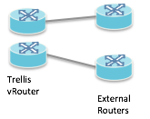
Dual External Routers
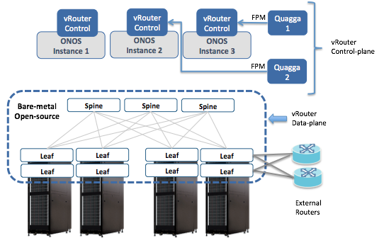
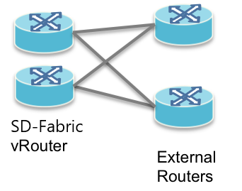
In addition to what we describe in External Connectivity, SD-Fabric also supports dual external routers, which view the SD-Fabric as 2 individual routers, as shown above.
As before the vRouter control plane is implemented as a combination of Quagga, which peers with the upstream routers, and ONOS which listens to Quagga (via FPM) and programs the underlying fabric. In dual-router scenarios, there are two instances of Quagga required.
As before the hardware fabric serves as the data-plane of vRouter. In dual-router scenarios, the external routers MUST be connected to paired-ToRs.
ToR connects to one upstream
Lets consider the simpler case where the external routers are each connected to a single leaf in a ToR pair. The figure on the left below shows the logical view. The figure on the right shows the physical connectivity.
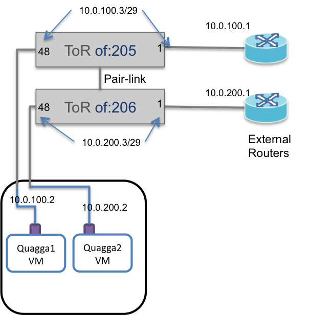
One of the upstream routers is connected to of:205 and the other is
connected to of:206. Note that of:205 and of:206 are paired ToRs.
The ToRs are connected via a physical port to separate Quagga VMs or containers. These Quagga instances can be placed in any compute node. They do not need to be in the same server, and are only shown to be co-located for simplicity.
The two Quagga instances do NOT talk to each other.
Switch port configuration
The ToRs follow the same rules as single router case described in External Connectivity. In the example shown above, the switch port config would look like this:
{
  "ports": {
    "of:0000000000000205/1" : {
      "interfaces" : [{
        "ips" : [ "10.0.100.3/29", "2000::6403/125" ],
        "vlan-untagged": 100,
        "name" : "internet-router-1"
      }]
    },

    "of:0000000000000205/48" : {
      "interfaces" : [{
        "ips" : [ "10.0.100.3/29", "2000::6403/125" ],
        "vlan-untagged": 100,
        "name" : "quagga-1"
      }]
    },

    "of:0000000000000206/1" : {
      "interfaces" : [{
        "ips" : [ "10.0.200.3/29", "2000::6503/125" ],
        "vlan-untagged": 200,
        "name" : "internet-router-2"
      }]
    },

    "of:0000000000000206/48" : {
      "interfaces" : [{
        "ips" : [ "10.0.200.3/29", "2000::6503/125" ],
        "vlan-untagged": 200,
        "name" : "quagga2"
      }]
    }
  }
}
Note
In the example shown above, switch of:205 uses VLAN 100 for
bridging the peering session between Quagga1 and ExtRouter1, while switch
of:205 uses VLAN 200 to do the same for the other peering session.
But since these VLANs and bridging domains are defined on different
switches, the VLAN ids could have been the same.
This philosophy is consistent with the fabric use of bridging.
Quagga configuration
Configuring Quagga for dual external routers are similar to what we described in External Connectivity. However, it is worth noting that:
The two Zebra instances should point to two different ONOS instances for their FPM connections. For example Zebra in Quagga1 could point to ONOS instance with
fpm connection ip 10.6.0.1 port 2620, while the other Zebra should point to a different ONOS instance withfpm connection ip 10.6.0.2 port 2620. It does not matter which ONOS instances they point to as long as they are different.The two Quagga BGP sessions should appear to come from different routers but still use the same AS number – i.e. the two Quaggas’ belong to the same AS, the one used to represent the entire SD-Fabric.
The two upstream routers can belong to the same or different AS, but these AS numbers should be different from the one used to represent the SD-Fabric AS.
Typically both Quagga instances advertise the same routes to the upstream. These prefixes belonging to various infrastructure nodes in the deployment should be reachable from either of the leaf switches connected to the upstream routers.
The upstream routers may or may not advertise the same routes. SD-Fabric will ensure that traffic directed to a route reachable only one upstream router is directed to the appropriate leaf.
ToR connects to both upstream
Now lets consider the more-complicated but more fault-tolerant case of each Quagga instance peering with BOTH external routers. Again the logical view is shown on the left and the physical view on the right.
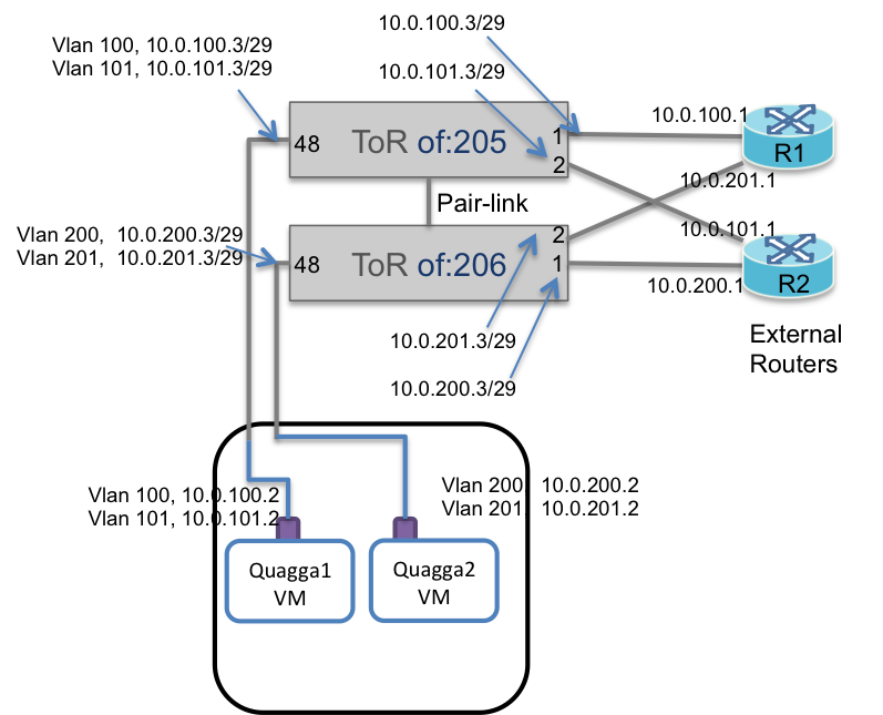
First lets talk about the physical connectivity
Quagga instance 1 peers with external router R1 via port 1 on switch of:205
Quagga instance 1 peers with external router R2 via port 2 on switch of:205
Similarly
Quagga instance 2 peers with external router R1 via port 2 on switch of:206
Quagga instance 2 peers with external router R2 via port 1 on switch of:206
To distinguish between the two peering sessions in the same physical switch, say of:205, the physical ports 1 and 2 need to be configured in different VLANs and subnets. For example, port 1 on of:205 is (untagged) in VLAN 100, while port 2 is in VLAN 101.
Note that peering for Quagga1 and R1 happens with IPs in the
10.0.100.0/29 subnet, and for Quagga 1 and R2 in the 10.0.101.0/29
subnet.
Furthermore, pair link (port 48) on of:205 carries both peering sessions to Quagga1. Thus port 48 should now be configured as a trunk port (vlan-tagged) with both VLANs and both subnets.
Finally the Quagga interface on the VM now needs sub-interface configuration for each VLAN ID.
Similar configuration concepts apply to IPv6 as well. Here is a look at the switch port config in ONOS for of:205
{
  "ports": {
    "of:0000000000000205/1" : {
        "interfaces" : [{
            "ips" : [ "10.0.100.3/29", "2000::6403/125" ],
            "vlan-untagged": 100,
            "name" : "internet-router1"
        }]
    },


    "of:0000000000000205/2" : {
        "interfaces" : [{
            "ips" : [ "10.0.101.3/29", "2000::7403/125" ],
            "vlan-untagged": 101,
            "name" : "internet-router2"
        }]
    },
    "of:0000000000000205/48" : {
        "interfaces" : [{
            "ips" : [ "10.0.100.3/29", "2000::6403/125", "10.0.101.3/29", "2000::7403/125" ],
            "vlan-tagged": [100, 101],
            "name" : "quagga1"
        }]

    }
  }
}