Network Configuration
SD-Fabric uses several different types of network configurations.
We only focus on devices and ports configuration in this section, which
are used to provide basic L2/L3 connectivity.
See Advanced Features Guide for advanced feature configurations.
Device Configuration
Each switch in SD-Fabric requires a device config.
{
  "devices" : {
    "device:leaf1" : {
      "segmentrouting" : {
        "ipv4NodeSid" : 101,
        "ipv4Loopback" : "192.168.0.201",
        "ipv6NodeSid" : 111,
        "ipv6Loopback" : "2000::c0a8:0201",
        "routerMac" : "00:00:00:00:02:01",
        "isEdgeRouter" : true,
        "adjacencySids" : []
      },
      "basic" : {
        "name": "Leaf1",
        "managementAddress": "grpc://10.128.100.51:9339?device_id=1",
        "driver": "stratum-tofino",
        "pipeconf": "org.stratumproject.fabric-spgw-int.montara_sde_9_5_0"
      }
    }
  }
}
device:leaf1: arbitrary globally unique identifier of the device, must always be prefixed withdevice:.ipv4NodeSid: IPv4 node segment ID, which is used as an MPLS label in forwarding IPv4 traffic. Can be arbitrary and should be globally unique.ipv4Loopback: IPv4 loopback address. Can be arbitrary, should be globally unique and should not be part of the same subnet(s) defined on the data plane ports (see port config).ipv6NodeSid: IPv6 node segment ID, which is used as an MPLS label in forwarding IPv6 traffic. Can be arbitrary and should be globally unique. Only required when using IPv6.ipv6Loopback: IPv6 loopback address. Can be arbitrary, should be globally unique and should not be part of the same subnet(s) defined on the data plane ports (see port config). Only required when using IPv6.routerMac: Router MAC address. Can be arbitrary and should be globally unique. This MAC address will be used to reply the ARP request for the loopback IP or the Interface IP that will be introduced later. (We recommend using the MAC address of the device’s management interface as the router MAC.)isEdgeRouter: True for leaf switches. False for spine switches.adjacencySids: Deprecated. Always use an empty array.name: Human friendly name used in the ONOS UI.managementAddress: gRPC endpoint of the Stratum device and the P4Runtime internal device ID associated to the ASIC (usually1), in the format ofgrpc://[device_addr]?device_id=[P4Runtime device ID]The IP address can be replaced by a domain name.driver:stratum-bmv2orstratum-tofino, depending on which switch this is.pipeconf: the P4 program to deploy on this switch. A list of available pipeconfs can be dumped by runningpipeconfsin the ONOS CLI. When running with Tofino-based devices, we provide pre-installed pipeconfs with IDorg.stratumproject.<profile>.<device-type>_<bf-sde-version>:The available profiles are:
fabric: for basic L2/L3 capabilitiesfabric-spgw: with 4G/5G mobile user plane supportfabric-int: with INT supportfabric-spgw-int: with SPGW and INT support
The supported device-types:
montara: for dual-pipe Tofino ASIC SKUsmavericks: for quad-pipe Tofino ASIC SKUs
The Intel/Barefoot SDE version used in Stratum, e.g.,
sde_9_5_0
Caution
You should avoid using reserved MPLS labels for ipv4NodeSid and
ipv6NodeSid. Please check here for the reserved values:
http://www.iana.org/assignments/mpls-label-values/mpls-label-values.xhtml
Note
Most of the SD-Fabric configurations support dynamic updates. Unfortunately, we currently do not support dynamic device configuration updates. You will have to restart (reboot) the switch if the corresponding device configuration changes.
Having said that, when introducing a completely new device in the network, the device configurations pushed before ONOS connects to the switch for the first time should be applied correctly.
Port IDs for Tofino-based devices
Before describing the ONOS netcfg, it is worth nothing how we refer to ports for
Tofino-based devices. Netcfg uses the format device:<name>/<port-number>.
<port-number> is a special value that is usually different than the number
shown in the switch front panel. It is the same number used for P4 table
programming and depends on the specific Tofino ASIC SKU (e.g., dual-pipe vs.
quad-pipe) and switch vendor/platform. In Stratum this is often referred to as
the SDK port ID, as this is the number used for all Tofino SDK calls. In Intel
documentation this is referred to as the DP_ID. We plan to remove this
dependency on such a low level detail in future releases, but for now, to find
out the mapping between front-panel ports and DP_ID you have the following
options:
Ask your switch vendor
Use the command pm.show on the BF shell of a running Stratum instance (see Troubleshooting Guide)
Bridging and Unicast Routing
In the following we illustrate how to enable basic bridging and routing on a per-port basis.
Attention
VLAN 4094 is reserved for unconfigured ports (e.g. spine facing ports)
VLAN 4090 is reserved for pseudowire transport flow rules on the spines
Access Ports
The necessary but minimum configuration for an access port is simply a VLAN.
{
  "ports" : {
    "device:leaf1/12" : {
      "interfaces" : [{
        "name" : "serverA-intf",
        "vlan-untagged": 10
      }]
    },
    "device:leaf1/16" : {
      "interfaces" : [{
        "name" : "serverB-intf",
        "vlan-untagged": 10
      }]
    }
  }
}
The example above shows two ports (12 and 16) on switch leaf1 that have
been assigned to VLAN 10 using the vlan-untagged keyword.
It simply means that packets come in and leave out of these switches untagged, but internally they are assigned VLAN 10 and they belong to the bridging domain defined for VLAN 10.
name is used to associate the interface with a globally unique, user
friendly name. It can be omitted.
With the configuration shown above, the packets will always be bridged, but they cannot be routed out of the VLAN (e.g. to other subnets). To add the capability to route out of VLAN 10, we need to add a subnet/gateway IP (similar to interface-vlans or SVIs in traditional networks).
{
  "ports" : {
    "device:leaf1/12" : {
      "interfaces" : [{
        "name" : "serverA-intf",
        "ips" : [ "10.0.1.254/24"],
        "vlan-untagged": 10
      }]
    },
    "device:leaf1/16" : {
      "interfaces" : [{
        "name" : "serverB-intf",
        "ips" : [ "10.0.1.254/24"],
        "vlan-untagged": 10
      }]
    }
  }
}
In this example, VLAN 10 is associated with subnet 10.0.1.0/24, and the
gateway IP for hosts in this subnet is 10.0.1.254/32.
When the desire is to route out of a VLAN, this assignment is currently necessary on all ports configured in the same VLAN.
Note
Typically we only expect a single subnet for a VLAN. Similar to traditional networks, for us, a subnet == VLAN. Different VLANs should be configured in different subnets.
In certain use-cases, it may be necessary to configure multiple subnets in
the same VLAN. This is possible by adding more subnet/gateway IPs in the
ips array.
Attention
The same subnet cannot be configured on multiple leaf switches.
We usually configure one subnet for all the ports on the same leaf switch.
Tagged Ports
Tagged port configuration is similar.
{
  "ports" : {
    "device:leaf1/24" : {
      "interfaces" : [{
        "name" : "serverA-intf",
        "ips" : [ "10.0.2.254/24", "10.0.4.254/24" ],
        "vlan-tagged" : [ 20, 40 ]
      }]
    }
  }
}
The configuration above for port 24 on switch leaf1 shows two VLANs 20 and
40 configured on that port, with corresponding subnets and gateway IPs.
Note that there is no specific ordering required in the ips or
vlan-tagged arrays to correlate the VLANs to their corresponding subnets.
In a future release, we will correlate VLAN and subnets configuration in a more readable way.
Native VLAN on Tagged Ports
An additional configuration vlan-native possible on tagged ports includes
the ability to specify a VLAN (and thus a bridging domain) for incoming
untagged packets.
Typically, such configuration in trunk ports in traditional networks is referred to a native VLAN.
{
  "ports" : {
    "device:leaf1/24" : {
      "interfaces" : [ {
        "name" : "serverA-intf",
        "ips" : [ "10.0.2.254/24", "10.0.4.254/24", "10.0.1.254/24" ],
        "vlan-tagged" : [ 20, 40 ],
        "vlan-native" : 10
      }]
    }
  }
}
Note that it is also necessary to configure the subnet/gateway IP corresponding to the native VLAN if you wish to route out of that VLAN.
Configuring interface for IPv6 1
It is similar to configure IPv6 routing. Simply replace the addresses in
ips with IPv6 addresses. For example:
{
  "ports" : {
    "device:leaf1/24" : {
      "interfaces" : [ {
        "name" : "serverA-intf",
        "ips" : [ "10.0.2.254/24", "2000::1ff/120" ],
        "vlan-tagged" : [ 20, 40 ]
      }]
    }
  }
}
Note
There is a known issue that breaks dynamic VLAN configuration. Until the issue get resolved, you need to restart the switch agent to reinstall the flows.
IPv6 Router Advertisement 1
Router Advertisement overview
Router advertisement application is for enabling Router Advertisement and Router Solicitation functionalities supported by IPv6 routers.
More details are available in RFC 4861.
Application identifies which IPv6 interfaces are currently configured in the system and it will try to send out unsolicited Router Advertisement (RA) messages from these interfaces.
Each such RA message will have two mandatory options named Source link-layer address and MTU.
Additional RA option prefix can be enabled using component configuration raGlobalPrefixConfStatus.
Application also processes Router Solicitations (RS) sent from hosts. Upon receiving RS on a particular interface application stops RA transmission in that interface and immediately sends RA targeted to the solicited host. After that application continues unsolicited RA transmission on that interface.
Activate and configure RA
RA application can be activated from CLI by running
onos> app activate routeradvertisement
Behavior of RA application is controlled by ONOS component configuration subsystem and following are possible configuration options.
raThreadDelay: Delay between consecutive RA transmissionsraPoolSize: Capacity of thread pool to be used for RA transmissionsraFlagMbitStatus: RA flag “Managed address configuration” enabled/disabledraFlagObitStatus: RA flag “Other configuration” enabled/disabledraOptionPrefixStatus: RA Option “prefix” is enabled/disabled. Router prefixes will be available in RA only if this flag is “true”raGlobalPrefixConfStatus: Enable switch level global prefix configuration. OnceraGlobalPrefixConfStatusis enabled, RA prefix option is generated from port configuration of device, see for more details.
To set the options, following the command (example for raOptionPrefixStatus)
onos> cfg set org.onosproject.ra.RouterAdvertisementManager raOptionPrefixStatus true
Prefix details are picked up from network interface configuration.
RA app will filter out link-local IPs while preparing prefixes.
For example, in following configuration, Prefix will include only 2001:0558:FF10:04C9::2:1ff/120.
{
  "ports": {
    "device:leaf2/16": {
      "interfaces": [{
        "ips": [ "192.168.114.1/24", "2001:0558:FF10:04C9::2:1ff/120", "FE80::4EA8:2AFF:FE24:8E5F/120" ],
        "vlan-untagged": "11",
        "name": "18-15"
      }]
    }
  }
}
Global prefix configuration
In some cases, users may want to have a set of global prefix advertised on all edge interfaces.
Such prefixes can be configured in devices section of network configuration in the following way.
{
  "devices": {
    "device:leaf2": {
      "routeradvertisement" : {
        "prefixes": [ "2001:0558:FF10:04C9::3:1ff/120"]
      }
    }
  }
}
Note
When global prefix is configured, RA app will ignore any prefixes configured on switch interfaces.
Notes about interface config
There is no need to configure ports on switches that are meant to connect to other switches.
The VLAN (untagged or tagged) configuration is only meant for ports that are connected to hosts (edge ports).
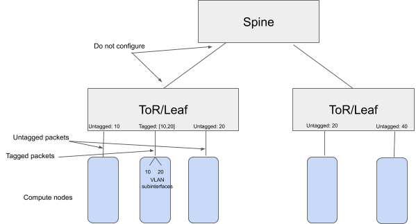
Furthermore, note that the same VLAN can be configured on multiple ToRs - e.g. VLAN 20 in the figure above.
However this does not mean that the ports are in the same bridging domain, because in the fabric, the communication between ToRs is through a routed network.
In other words, a host on VLAN 20 (untagged or tagged) connected to one ToR can communicate with another host on VLAN 20 (untagged or tagged) connected to a different ToR, but the MAC addresses will change as the traffic goes through a routed network.
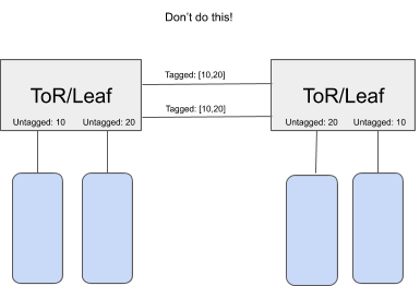
Please do not use this feature to connect switches in unsupported topologies as shown in the example below.
The fabric is not designed to be one big Ethernet fabric. The bridging domain is restricted to one ToR.
If the bridging domain is extended across two ToRs directly linked to each other, there is a chance of loops.
In other words, the ToRs/Leafs are not standalone 802.1Q bridges, and should not be used as such.
Footnotes