External Connectivity
vRouter
Physical Connectivity
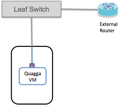
External routers must be physically connected to one of the fabric leaf switches.
Currently there is a limitation that the external/upstream router and the Quagga instance must be connected to the same fabric leaf switch.
Therefore it is necessary to use an additional front panel port on the leaf-switch (or at least an additional VLAN) to connect to the compute node hosting Quagga.
Configure vRouter
The operator will need to configure a subnet between the Leaf-switch, the external/upstream router and the Quagga instance. There are 3 IP addresses we need to allocate - 1 on the switch port, 1 in Quagga, and 1 on the upstream router. This means the peering subnet cannot be smaller than a /29.
BGP peering happens between the IP addresses configured on the interfaces in Quagga and the external router.
Routes are advertised by Quagga to the upstream with the next-hop set to the switch port IP address. This means that when traffic comes to the fabric leaf switch from outside, the switch is able to distinguish peering traffic from data traffic and treat each appropriately.
The following shows an ONOS interface configuration example:
{
  "ports" : {
    "of:0000000000000001/1" : {
      "interfaces" : [
        {
          "name" : "upstream1",
          "ips"  : [ "10.0.1.2/24" ],
          "vlan-untagged" : 4000
        }
      ]
    },
    "of:0000000000000001/2" : {
      "interfaces" : [
          {
            "name" : "quagga",
            "ips"  : [ "10.0.1.2/24" ],
            "vlan-untagged" : 4000
          }
      ]
    }
  }
}
name: An arbitrary name string for the interface. Optional.ips: Configure the peering subnet (10.0.1.0/24) and the switch port IP (10.0.1.2). Note that we use the same IP address on both the Quagga and upstream interfaces.vlan-untagged: Configure the same VLAN ID on both interfaces. It doesn’t matter exactly what the VLAN ID is, but it must be the same on both the Quagga-facing and upstream-facing interfaces.
In this case the peering subnet is 10.0.1.0/24.
The upstream router is using the 10.0.1.1 address.
Quagga is assigned 10.0.1.3, which is the address used for peering.
The upstream router needs to be configured with 10.0.1.3 as its BGP
neighbor, and the BGP peering will be established between 10.0.1.1 and
10.0.1.3. The 10.0.1.2 address is used by the fabric switch and for the
next-hop for routes advertised by Quagga.
Of course you are not obliged to use 10.0.1.0/24, you should use a subnet
that makes sense for your peering environment.
Note
This configuration will set up an L2 link between the two fabric switch ports, over which the Quagga and external router can communicate.
Both Quagga and the upstream router will receive untagged packets (i.e they will never see packets with VLAN id 4000, which is used inside the leaf switch to establish a bridging domain).
If you need a VLAN tag in the compute node to distinguish the traffic going
to Quagga, you can change the VLAN assignment on the switch port
“of:0000000000000001/2” to be vlan-tagged instead of vlan-untagged.
Deploy the Quagga Docker Image
SD-Fabric uses a slightly modified version of Quagga, so the easiest way to deploy this is to use the provided docker image.
$ docker pull opencord/quagga
We also need to download the pipework tool which will be used to connect the docker image to the physical interface that we set aside earlier.
$ wget https://raw.githubusercontent.com/jpetazzo/pipework/master/pipework
$ chmod +x pipework
Create a directory for your Quagga configuration files, and create a bgpd.conf
and zebra.conf in there. This folder is going to be mounted into the Quagga
container. More on configuring Quagga later.
$ mkdir configs
$ touch zebra.conf bgpd.conf
Now run the docker image (make sure the path the config directory matches what is on your system):
$ sudo docker run --privileged -d -v configs:/etc/quagga -n quagga opencord/quagga
Finally, we can use the pipework tool to add the physical interface into the container so that Quagga can talk out over the fabric:
$ sudo ./pipework mlx1 -i eth1 quagga 10.0.1.3/24
This will add host interface mlx1 to the container with name quagga
with interface name eth1 inside the container. The newly added interface
will have the IP 10.0.1.3. This IP address should be the peering subnet
address that you want to assign to Quagga.
If you need to change anything about the container (for example if you change the Quagga configuration) you can remove the original container and run a new one:
$ sudo docker rm -f quagga
$ sudo docker run --privileged -d -v configs:/etc/quagga -n quagga opencord/quagga
Configure Quagga
At this point Quagga should have IP connectivity to the external routers, and it should be able to ping them on the peering subnet.
Now Quagga and the upstream routers can be configured to peer with one another. This configuration of Quagga is going to be highly dependent on the configuration of the upstream network, so it won’t be possible to give comprehensive configuration examples here.
It is recommended to consult the Quagga documentation for exhaustive information on Quagga’s capabilities and configuration. Here I will attempt to provide a few basic examples of Quagga configuration to get you started. You’ll have to enhance these with the features and functions that are needed in your network.
Zebra configuration
Regardless of which routing protocols you are using in your network, it is important to configure Zebra’s FPM connection to send routes to the FPM app running on ONOS. This feature was enabled by the patch that was applied earlier when we installed Quagga.
A minimal Zebra configuration might look like this:
!
hostname cord-zebra
password cord
!
fpm connection ip 10.6.0.1 port 2620
!
The FPM connection IP address is the IP address of one of the ONOS cluster
instances - does not matter which one. If you have other configuration that
needs to go in zebra.conf you should add that here as well.
BGP configuration
An example simple BGP configuration for peering with one BGP peer might look like this:
hostname bgp
password cord
!
ip prefix-list 1 seq 10 permit 192.168.0.0/16
!
route-map NEXTHOP permit 10
match ip address prefix-list 1
set ip next-hop 10.0.1.2
!
router bgp 65535
  bgp router-id 10.0.1.3
  !
  network 192.168.0.0/16
  !
  neighbor 10.0.1.1 remote-as 65540
  neighbor 10.0.1.1 description upstream1
  neighbor 10.0.1.1 route-map NEXTHOP out
  !
This configuration peers with one upstream router 10.0.1.1 and advertises
one route 192.168.0.0/16. Note that Quagga (and as a result SD-Fabric) is in
a different AS 65535 from the upstream router AS 65540, as we are using
E-BGP for this connectivity.
Note
Pay attention to the configuration to rewrite the next hop of routes that are advertised to the upstream router.
A route-map is used to set the next hop of advertised routes to
10.0.1.2, which is different from the address that Quagga is using to
peer with the external router.
As mentioned above, it is important that this rewriting is done correctly so that the fabric switch is able to distinguish data plane and control plane traffic.
Route service and static route
Access route service via CLI
View routes
This will show routes from all sources, including static and dynamic routes.
The example below shows routes learned from the upstream router (Source: FPM) and routes configured manually (Source: STATIC)
onos> routes

B: Best route, R: Resolved route

Table: ipv4
B R  Network            Next Hop        Source (Node)
     0.0.0.0/0          172.16.0.1      FPM (127.0.0.1)
> *  1.1.0.0/18         10.0.1.20       STATIC
> *  10.0.99.0/24       10.0.1.1        FPM (127.0.0.1)
  *  10.0.99.0/24       10.0.6.1        FPM (127.0.0.1)
   Total: 2

Table: ipv6
B R  Network                                     Next Hop                                Source (Node)
> *  2000::7700/120                              fe80::288:ff:fe00:1                     FPM (127.0.0.1)
> *  2000::8800/120                              fe80::288:ff:fe00:2                     FPM (127.0.0.1)
> *  2000::9900/120                              fe80::288:ff:fe00:1                     FPM (127.0.0.1)
  *  2000::9900/120                              fe80::288:ff:fe00:2                     FPM (127.0.0.1)
   Total: 3
Add a static route
onos> route-add <prefix> <nexthop>
onos> route-add 1.1.0.0/18 10.0.1.20
onos> route-add 2020::101/120 2000::1
Remove a static route
onos> route-remove <prefix> <nexthop>
onos> route-remove 1.1.0.0/18 10.0.1.20
Access route service via REST
Single route
$ curl --user onos:rocks -X POST -H 'Content-Type:application/json' http://<controller-ip>:8181/onos/routeservice/routes -d@routes.json
$ curl --user onos:rocks -X GET -H 'Accept:application/json' http://<controller-ip>:8181/onos/routeservice/routes | python -mjson.tool
$ curl --user onos:rocks -X DELETE -H 'Content-Type:application/json' http://<controller-ip>:8181/onos/routeservice/routes -d@routes.json
with identical json format for both POST and DELETE:
{
  "prefix": "20.0.0.1/24",
  "nextHop": "10.0.1.10"
}
Bulk routes
$ curl --user onos:rocks -X POST -H 'Content-Type:application/json' http://<controller-ip>:8181/onos/routeservice/routes/bulk -d@routes.json
$ curl --user onos:rocks -X DELETE -H 'Content-Type:application/json' http://<controller-ip>:8181/onos/routeservice/routes/bulk -d@routes.json
with identical json format for both POST and DELETE:
{
  "routes": [
    {
      "prefix": "20.0.0.1/24",
      "nextHop": "10.0.1.10"
    },
    {
      "prefix": "30.0.0.1/24",
      "nextHop": "10.0.2.15"
    }
  ]
}
Verify routes
Check the leaf switches that the route (e.g. 1.1.0.0/18) has been programmed in the routing table (table 30).
onos> flows any of:0000000000000205 30
<snip>
id=670000d1f6782c, state=ADDED, bytes=0, packets=0, duration=39, liveType=UNKNOWN, priority=36010, tableId=30, appId=org.onosproject.segmentrouting, payLoad=null, selector=[ETH_TYPE:ipv4, IPV4_DST:1.1.0.0/18],
 treatment=DefaultTrafficTreatment{immediate=[], deferred=[GROUP:0x70000014], transition=TABLE:60, meter=None, cleared=false, metadata=null}
<snip>
Notes about next hops
The next hop of a route should be resolvable to a MAC address that is known to
ONOS. Typically the next hop is a server interface that is known to ONOS as a
host learned via ARP or DHCP. If you are not sure, check the hosts command
on the ONOS CLI.
onos> hosts
<snip>
id=A2:9B:32:9D:7F:B3/None, mac=A2:9B:32:9D:7F:B3, location=of:0000000000000205/48, vlan=None, ip(s)=[192.168.101.2], configured=false
id=B2:A4:E2:72:D1:91/None, mac=B2:A4:E2:72:D1:91, location=of:0000000000000204/16, vlan=None, ip(s)=[10.0.1.20], configured=false
id=EE:22:F7:BE:86:50/None, mac=EE:22:F7:BE:86:50, location=of:0000000000000205/16, vlan=None, ip(s)=[10.0.2.15], configured=false
If the next hop has not been resolved for any reason, it would be necessary to configure the next hop as a host (/32 prefix) together with MAC address and location.
Learn more about how to configure a host using Network Config Host Provider
Finally note that if you are configuring routes manually/statically and they are publicly routable IPs that should be reachable from “outside”, you would need to configure Quagga to advertise them upstream.
Route blackhole
The blackhole consists of a rule on table 30 on every edge device on the
fabric. The Table 30 rule matches on a given IP address and mask and has
nothing but a clearDeferred action, practically dropping the packet. Every IP
we want to blackhole will have it’s own rule in every edge switch.
An example of such rule is:
ADDED, bytes=0, packets=0, table=30, priority=48010, selector=[ETH_TYPE:ipv4, IPV4_DST:50.0.0.0/24], treatment=[transition=TABLE:60]
Route blackholing can be done via network configuration.
{
  "apps" : {
    "org.onosproject.segmentrouting" : {
      "segmentrouting": {
        "blackholeIps": [
          "50.0.0.0/24"
        ]
      }
    }
  }
}
Ignore certain FPM peer
The FpmConnectionInfo consists a new flag acceptRoutes, indicating
whether we want to accept or discard the routes advertised by certain FPM peer.
Per current requirement, we always have the acceptRoutes flag set to
true by default, meaning that we will accept routes from all peers.
We can updated the flag using REST API and CLI command as below
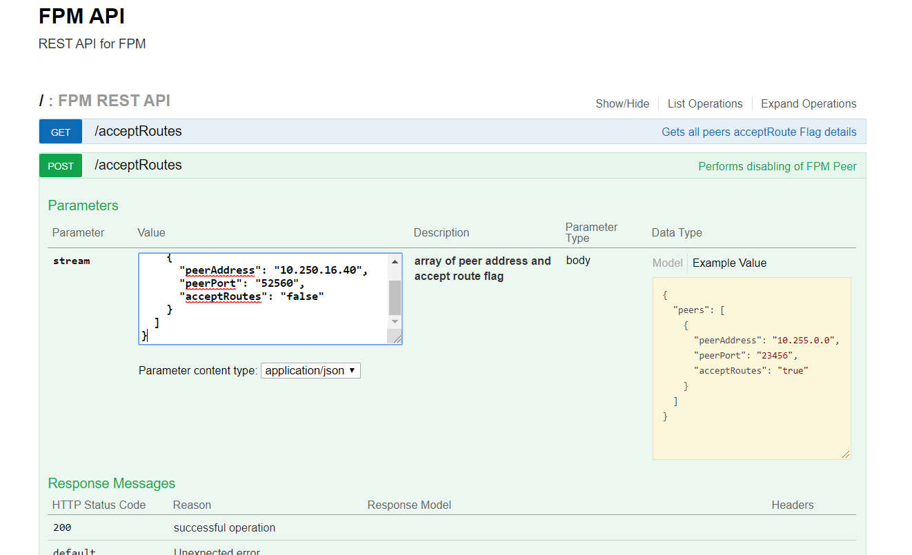
REST API
POST /acceptRoutesto enable or disableacceptRoutesflagGET /acceptRoutesto fetch the current status of the FPM connection
CLI
fpm-set-accept-routesto enable or disableacceptRoutesflagonos> fpm-set-accept-routes 10.250.16.40 52560 falsefpm-get-accept-routeto fetch the current status of the FPM connectiononos> fpm-get-accept-route <snip> peer 10.250.16.40 port 52560 acceptRoutes false peer 10.250.16.41 port 52594 acceptRoutes true <snip>